I think a bunch of half adder circuits are adequate here you can copy those out of your textbook right. Designing a very simple 2s complement circuit on proteus showing the circuits details.
Each inverted output goes to a 2 bit adder an xor paralleled with an and.

2 complement circuit diagram. It has only two digits 0 and 1 and hence the name is binary. It has a base of 2 so if we subtract it from the highest number of that digit then we get 2 1 that is 1s complement. Twos complement representation is a way to represent the signed numbers in a digital computer.
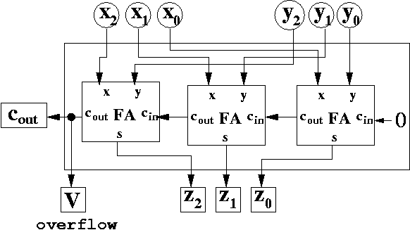
4 bit parallel adder using full adders and lab pin diagram 7483 ic duration. There are at least 2 ways to get the 2s complement of a number in a sipo shift register. The following diagram is a 1 bit full adder.
Now coming to a binary number which is our main topic for discussion. The 1 bit full adder accepts two bits plus a carry input and generates the sum of the two bits plus a carry output. A 4 bit adder is constructed using four stages of a 1 bit full adder.
In this scheme if the binary number 010 2 encodes the signed integer 2 10 then its twos complement 110 2 encodes the inverse. Digital system cc01 tut 3 pham le song ngan duong doan thai thinh. Remember that with 2s complement the msb is attached to a weigting that is negative while for all the other bits the weightings attached are positive powers or 2.
In other words to reverse the sign of any integer in this scheme. Twos complement is the most common method of representing signed integers on computers. The extra 1 is entered at the first xor spare input.
We can cascade four of the 1 bit full adder stages together. Take the 4 bits of the value simultaneously invert all the bits and simultaneously add one. Twos complement using only logic gates.
In this way we will be able to use the same circuit to perform both addition and subtraction. So the logic about which is greater is reversed for the msb. The carry from each lower adder and feeds to the next higher xor input.
The main goal is to develop a technique which replaces a subtraction operation with an addition.


0 Response to "2 Complement Circuit Diagram"
Post a Comment